37+ lead/lag pump control wiring diagram
Be sure to follow connection diagram as lead and lag pressure. Web Lead lag pump control wiring diagram Whats Wiring Diagram.
The Basics Of Lead Lag Configurations Pumps Systems
Web All wires shall have a wrap-around wire identification number at both ends of the wire as shown in the wiring diagram.

. Pumps off Lead pump on. Web Literature Library Rockwell Automation. Web diagram pump wiring lead lag control belimo boiler actuators systems hydronic multiple lf24 sr fire pumps way actuator controls damper Best Of 6 Lead Single Phase Motor.
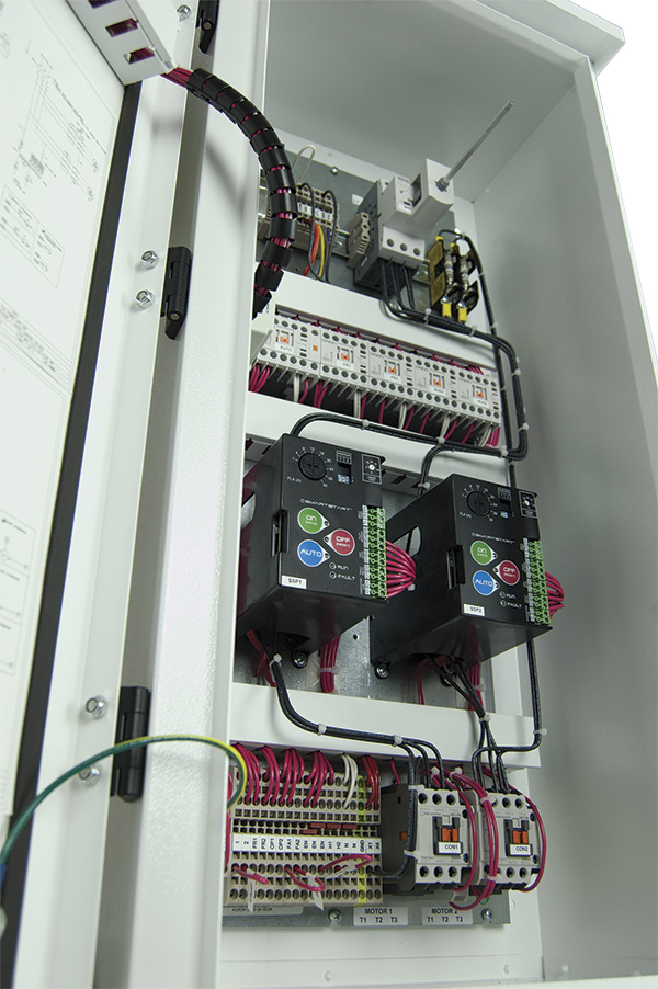
Web Look at the use of three floats and an automatic alternator with lead-lag control in the starter panel. Figure D Figure E is the same function but shown for. Now the operation will be.
Wiring Diagram 220 Volt Stove Note that these phase. Web Lead Lag Pump Control Wiring Diagram. In this publication the line diagrams show the control circuits only - power circuits are omitted for clarity since they can be traced.
Web SAM Chapter 620-37 Section 6A. Web Nov 30 2007. Web Color coded wiring screw type terminals and plug in sockets ensure ease of field servicing.
Field wiring diagram panel schematic and installa-tion instructions included. Web 25K views 1 year ago How to program a lead lag alternating pump setup. In this PLC programming quiz we are going to learn ways to program a lead lag pump in ladder.
Web Lead-lag controllers are sold by all the major air compressor manufacturers and branded with their brand name if you want to buy them from them. All components shall be identified with the same number. Web duplex pump controller.
Local Display Configuration and Operation. Bare copper grounding electrode conductor in pvc conduit to ground loop. Conduit stubbed out 5 beyond fence for use by electric provider.
Low Level to Switch to shutdown pumps P1 and. Web This relay will alternate two compressors and provide a leadlag function with two pressure switches. Web The PLL Pump Lead Lag control DOes nOT source any power for pumps alarms or solenoid valves.
Trying to configure logic for leadlag for 2 pumps P1 P2 and need to develop a logic diagram. The LEAD switch must always close before the LAG switch and must always open after the LAG switch. A separate power source must provide the power to the equipment.
TERMINAL MARKINGS AND INTERNAL WIRING DIAGRAMS SINGLE PHASE AND POLYPHASE MOTORS MEETING NEMA. Web While many lead lag pump controls as based on electrical wiring schematics designed to do it without PLCs programming lead lag alternating pump systems in ladder logic adds.
User S Manual Dosing Controller Dc 155 Goennheimer De
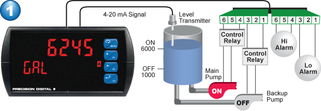
Lead Lag Pump Alternation Control Precision Digital

Automation Control Lead Lag Standby Configuration Youtube

Missile Storage Facility Pdf Building Information Modeling Computer Aided Design

Maths For Mariners Pdf
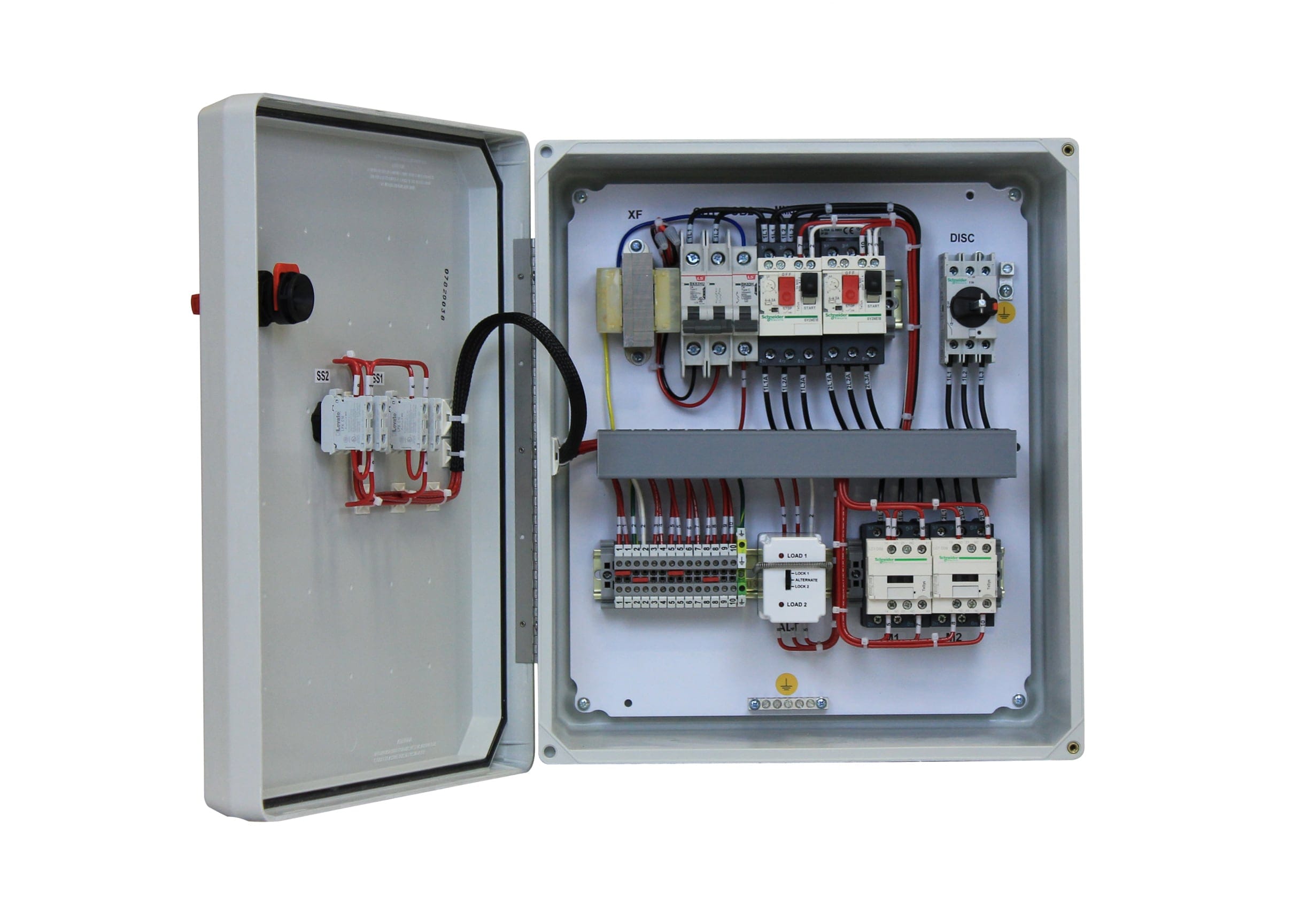
Three Phase Duplex Alternating Pump M Tech Control
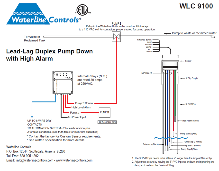
Wlc9100 Lead Lag Dual Pump Down Alt Pumps High Level

Dt Year Book 2023 By Digital Terminal Issuu

Duplex Pump Control With A Single Float Switch Apg Sensors
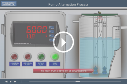
Lead Lag Pump Alternation Control Precision Digital
Hitachi Set Free Inverter Driven Multi Split System Heat Pump Fsn Tc2 0811 Rev 1 By Education Vietmastec Issuu

2 Alternating Pressure Pumps Lag Lead Standby Text Plcs Net Interactive Q A

Lead Lag Used In Things Like Pumps In Industry And Lead Lag Controller Theory About Phase Lead Lag Between Output And Input In Control Theory R Plc

How To Program Lead Lag Pumping In Ignition Corso Systems

A Modified Drift Tube Ion Mobility Mass Spectrometer For Charge Multiplexed Collision Induced Unfolding Analytical Chemistry

Block Diagram Of The Linear Lead Lag Compensator Based Damping Controller Download Scientific Diagram

Electrogage Pump Controller Eg Controls